
Pogo pins, also known as spring contact pins, enable compact and repeatable contacting in test systems, docking interfaces and modular interconnection solutions. etronics supports you in selecting, specifying and procuring suitable standard or custom pogo pin solutions.

Pogo pins: benefits for your application
Pogo pins are suitable wherever electrical contacts need to perform reliably, save space and withstand many cycles. Key factors include spring force, stroke, tip geometry, pitch, contact surface and integration into the respective assembly.
Your benefits:
-
Repeatable contacting through defined spring force and suitable tip geometries
-
Long service life: depending on design up to 1,000,000+ contact cycles with stable electrical characteristics
-
Compact form factor for space-saving, high-density designs
-
Flexible integration: SMT/SMD (reflow) and THT, as a single pin or as a contact assembly
-
Special variants: e.g. high-current and RF pogo pins as well as IP-rated and magnetic solutions
-
Custom options: length, stroke/spring force, tip design, as well as plating/surface finish and material pairing
What matters when using pogo pins
Whether test adapter, docking station, service interface or modular assembly: pogo pins are used wherever electrical contacts need to be made frequently, compactly and repeatably. What matters is not only the individual spring contact pin, but the interaction of spring force, stroke, contact geometry, contact surface, mating contact and mechanical guidance.
Pogo pin connectors & contacting solutions
Many applications require not just “one” pogo pin, but a complete contacting solution: several spring contact pins in an array or strip, defined mating parts and mechanical guidance for secure docking and tolerance compensation. Such solutions are particularly useful when positioning, repeatability and serviceability are key – for example in docking, testing or modular assemblies.
Typical application areas for such contacting solutions:
- Test, programming & service applications
Temporary contacting for test fixtures, flashing, debugging, calibration and diagnostics of printed circuit boards, assemblies and modules. - Docking, charging & power transmission
Repeatable docking as well as battery and charging contacting for energy and data transmission – including in connectors and cable systems. - Pluggable & modular connections
Board-to-board contacting and defined contact points for modular, replaceable units or cable-based connections without conventional connectors. - Space-critical & mechanically demanding applications
Reliable contacting in limited installation space, with high cycle counts as well as tolerances, movement or vibration. - Environmentally demanding applications
Use in humid, dusty or vibration-prone environments, e.g. with IP-protected pogo pin variants.
The following section presents key variants – including high-current, RF, SMT/SMD, IP-protected and magnetic pogo pin solutions.
Which pogo pin solution fits your application?
Custom pogo pin solutions
In addition to standard versions, customised pogo pin solutions are also possible – for example with adapted form factor, spring force, stroke, tip geometry, surface finish, pitch, housing integration or a complete connector/assembly solution.
Standard pogo pins
Test adapters, contacting, modular interfaces and general connection tasks.
Spring force, stroke, tip geometry, pitch and service life.
Waterproof pogo pins
Outdoor devices, robust interfaces and applications exposed to moisture.
IP protection, sealing, material selection, surface finish and mechanical integration.
Magnetic pogo pin connectors
Charging and docking solutions, quick-release connections and convenient contacting.
Holding force, polarity, contact stability, positioning and ease of use.
High-current pogo pins
Power transmission, charging and supply contacts as well as compact power connections.
Current carrying capacity, contact resistance, heat development and material pairing.
High-frequency pogo pins
RF applications, measurement and testing technology as well as signal transmission at high frequencies.
Impedance, signal quality, frequency range, contact geometry and layout integration.
SMD pogo pins
SMT assembly, compact PCB integration and automated production.
Form factor, soldering process, positioning, footprint and assembly suitability.
Technical selection criteria in detail
For precise specification, the relevant mechanical, electrical and application-specific parameters should be checked in detail.
Mechanics / Form factor
- Form factor
- Standard, waterproof (IP67/68), magnetic, RF-suitable, high-current variants
- Mounting type
- SMT/SMD, THT, connector, customised assemblies (depending on application)
- Pitch / Spacing
- Distance between contacts (e.g. 0.8–2.54 mm or customised)
- Stroke
- Spring travel / compression travel – influences contact reliability
- Tip geometry
- Crown, dome, flat, pointed or customised depending on the mating contact (flat surface, round contact, etc.)
Electrical data
- Rated current / Current carrying capacity
- Specified in A – standard usually 0.5–15 A; high-current pins >30 A possible
- Contact resistance
- Typically <30 mΩ (depending on design and plating)
- Voltage
- Up to approx. 60 V depending on insulation & design
Service life & Environment
- Contact cycles
- Service life in cycles (up to >1 million possible depending on type)
- Temperature range
- e.g. −40 °C to +85 °C or more depending on design
- Protection rating / IP
- Water and dust protection – e.g. IP67/IP68-capable variants
Material & Surface finish
- Contact surface
- Gold plating typically 0.25–1.0 µm for low oxidation & low resistance
- Housing / Plunger
- Copper alloys, stainless steel (depending on material)
Special product categories
- Standard pogo pins
- Universally applicable
- Waterproof pogo pins
- For outdoor/moist environments up to IPX8
- Magnetic pogo connectors
- For automatic alignment & convenient plug-in connection
- High-current pins
- For high power transmission, special design
- High-frequency pins
- For RF/data transmission (e.g. 5G+)
- Ultra-small pins
- For compact electronics & miniature devices
- Screw pins / Mounting pins
- Combined fastening + contact function
Design & procurement support
- CAD data & footprints
- 2D/3D CAD, footprint recommendations for layouting
- Selection support
- Parameter matching, variant comparison, risk notes
- Samples & data
- Samples, datasheets, 2D/3D CAD available
- Procurement / Supply chain
- Reliable supply chain, alternatives & obsolescence checks
Pogo pin variants for different requirements
Depending on the application, pogo pins differ in form factor, spring force, stroke, contact geometry, current-carrying capacity, protection rating and mounting method. The following variants show typical solutions for testing, docking, power transmission, high-frequency applications and custom interconnection systems.
Standard pogo pins
Standard pogo pins (spring contact pins) are the basis for many applications – from direct contacting of pads to integration into contact strips and assemblies. Key selection factors include installation space, stroke, spring force, tip geometry and plating. When standard sizes, fast availability or a robust series solution are required, we use a small number of parameters to identify suitable variants and possible alternatives.
Key selection parameters:
- Installation height / available space and mechanical tolerances
- Stroke and spring force matched to the contact surface
- Tip geometry (e.g. crown/dome/flat) for pads or mating contacts
- Plating/material pairing (contact stability, wear, corrosion)
- Single contact vs array/assembly (guidance/positioning)
- Optional: mounting method (e.g. SMT/SMD soldering vs other fixing methods)
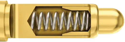
Waterproof pogo pins (IP67/IP68)
For applications with moisture, splash water or cleaning cycles, IP-rated pogo pins are used. Not only sealing and materials are decisive, but also the correct integration into the housing and mating contact – so that the IP rating is achieved in real operation and contacting remains stable long-term.
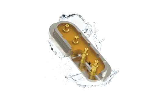
Magnetic pogo pin connectors
Magnetic pogo pin connectors simplify mating when fast handling, defined positioning or a robust docking interface are important. Relevant factors are magnetic guidance, contact geometry and mechanical stability so that the contact remains repeatable over many cycles.
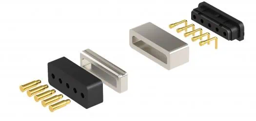
High-current pogo pins
High-current pogo pins (high-current contact pins) are designed for applications in which spring contact pins must transfer not only signals but also significant currents safely – e.g. docking interfaces, power handover points or power-near modules. The overall interface concept is decisive: contact area, spring force, materials/plating, thermal behavior and mechanical guidance.
Key selection parameters:
- Current profile (rated current, peaks, duty cycle)
- Contact surface & spring force (stability, wear resistance)
- Material pairing / plating (corrosion, abrasion)
- Mechanical guidance (avoid lateral forces, ensure repeatable docking)

High-frequency pogo pins (RF)
RF pogo pins are used when defined signal transmission properties are required in addition to mechanical contacting. Geometry, integration of pin, mating contact and surrounding design, contact stability and repeatable mechanical guidance have a major influence on performance. For RF applications, we therefore always consider the complete interface – not just the individual spring contact.
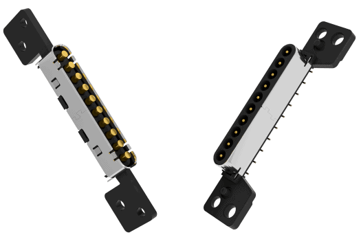
SMD pogo pins (for SMT assembly)
SMD pogo pins are designed for SMT assembly and reflow soldering and are particularly suitable for compact PCB interfaces. They are a good choice when manufacturability in series production, repeatable assembly and minimal installation space are key – for example, PCB-level docking contacts or test-near interfaces.SMD-Pogo-Pins sind für SMT-Bestückung und Reflow-Löten ausgelegt und eignen sich besonders für kompakte PCB-Interfaces. Sie sind sinnvoll, wenn Serientauglichkeit, reproduzierbare Montage und geringer Bauraum im Vordergrund stehen – etwa bei Docking-Kontaktierung auf Leiterplattenebene oder bei testnahen Schnittstellen.
Layout and process notes (SMT/SMD):
- Footprint/pad layout (coplanarity, solder volume)
- Mechanical concept (guidance/support against lateral forces)
- Process window (reflow, cleaning, mechanical load)
- Tip geometry/plating matched to the mating surface

Custom pogo pin solutions
When standard sizes do not fit, pogo pins and contact assemblies can be customised – for example for special installation heights, specific tip geometries, IP requirements or defined electrical targets for current and signal transmission. We support specification, variant comparison, sampling and procurement – with a focus on a robust series solution.
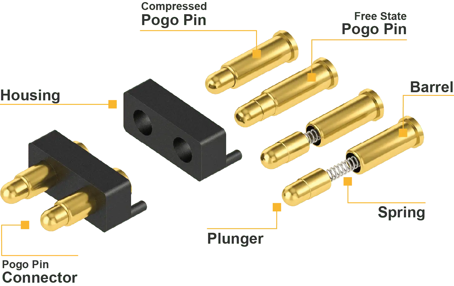
Our strengths in pogo pin solutions
With pogo pins, the right form factor is only one part of the solution. What matters is the interaction of contact quality, service life, manufacturing depth and reliable integration into the application.
- Technology leader in pogo solutions: extensive know-how in pogo pin design and modular connector design, including automated manufacturing processes
- Durable quality & high cycle life: pogo pins with lifetimes of up to 1 million cycles with consistently low contact resistance
- Flexible designs for any application: from miniature form factors <1 mm to high-performance power & signal transfer – precisely matched spring contacts for every installation situation
- High vertical integration & quality assurance: all products undergo 100% electrical & mechanical testing and are designed for long-term stability and environmental resistance
Applications
- Test systems & test fixtures: For ICT, FCT, wafer-level tests and PCB contacting – precise, repeatable contacting without soldering on the DUT
- Portable & mobile devices: Interconnect solutions for wearables, smartwatches, headsets or mobile scanners – depending on design also with magnetic guidance and IP protection
- Automotive & e-mobility: Charging contacts, onboard electronics and ECU testing – robust, vibration-resistant and designed for repeatable docking
- Medtech: Contacting in diagnostic systems, patient interfaces and medical docking solutions – for frequent mating cycles and defined contacting
- Industrial & automation: Contacting of moving parts, modular systems or robust sensor/actuator connections – reliable even under load and in harsh environments (depending on design)
Conclusion:
Pogo pins (spring contact pins) are a robust solution for compact, repeatable contacting – from standard variants to high-current, RF and SMT/SMD designs as well as IP-rated and magnetic interfaces. For stable electrical characteristics over many contact cycles, the coordinated interface of pin, mating contact and mechanical guidance is decisive. We support you from selection through reliable sourcing.
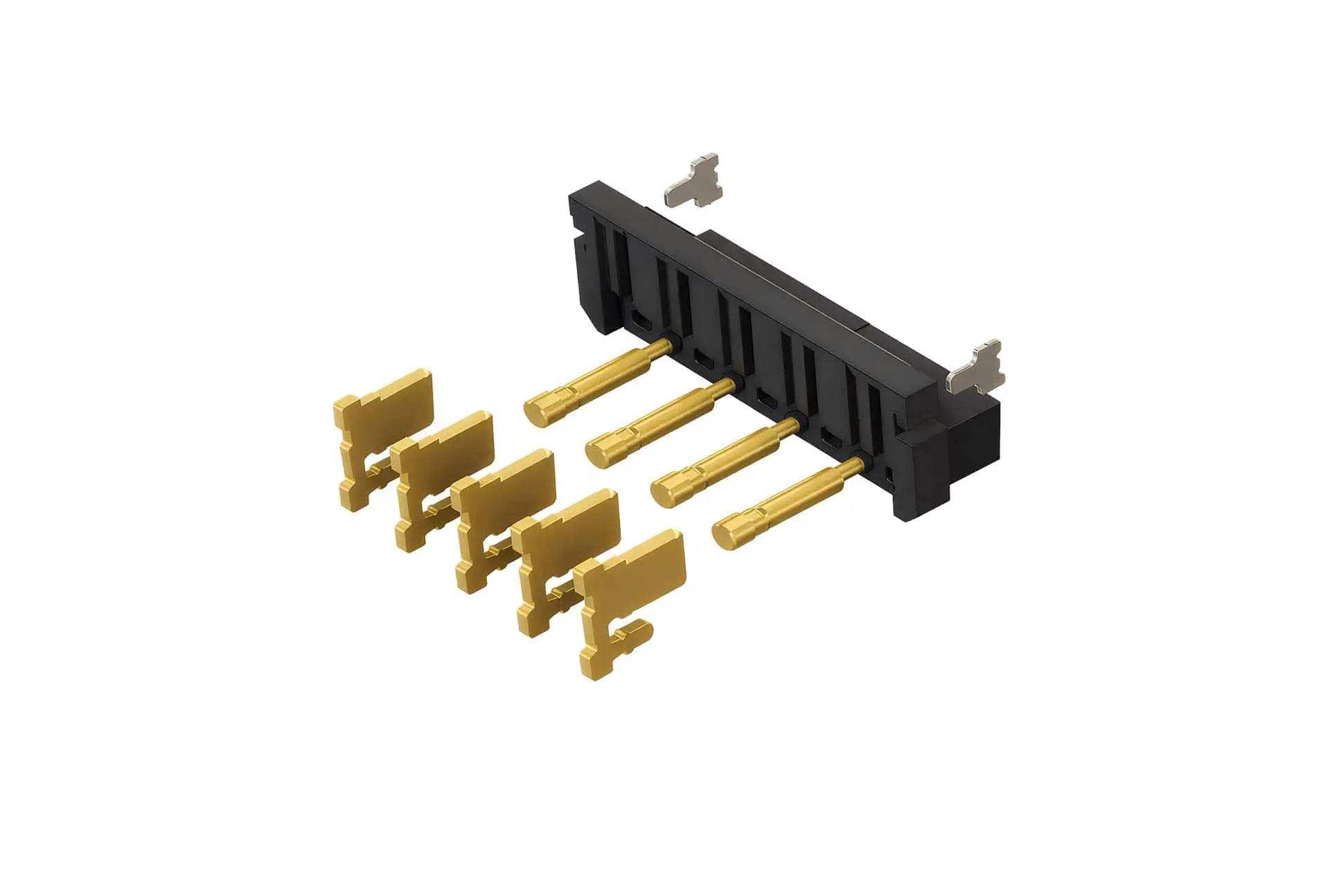
More product images
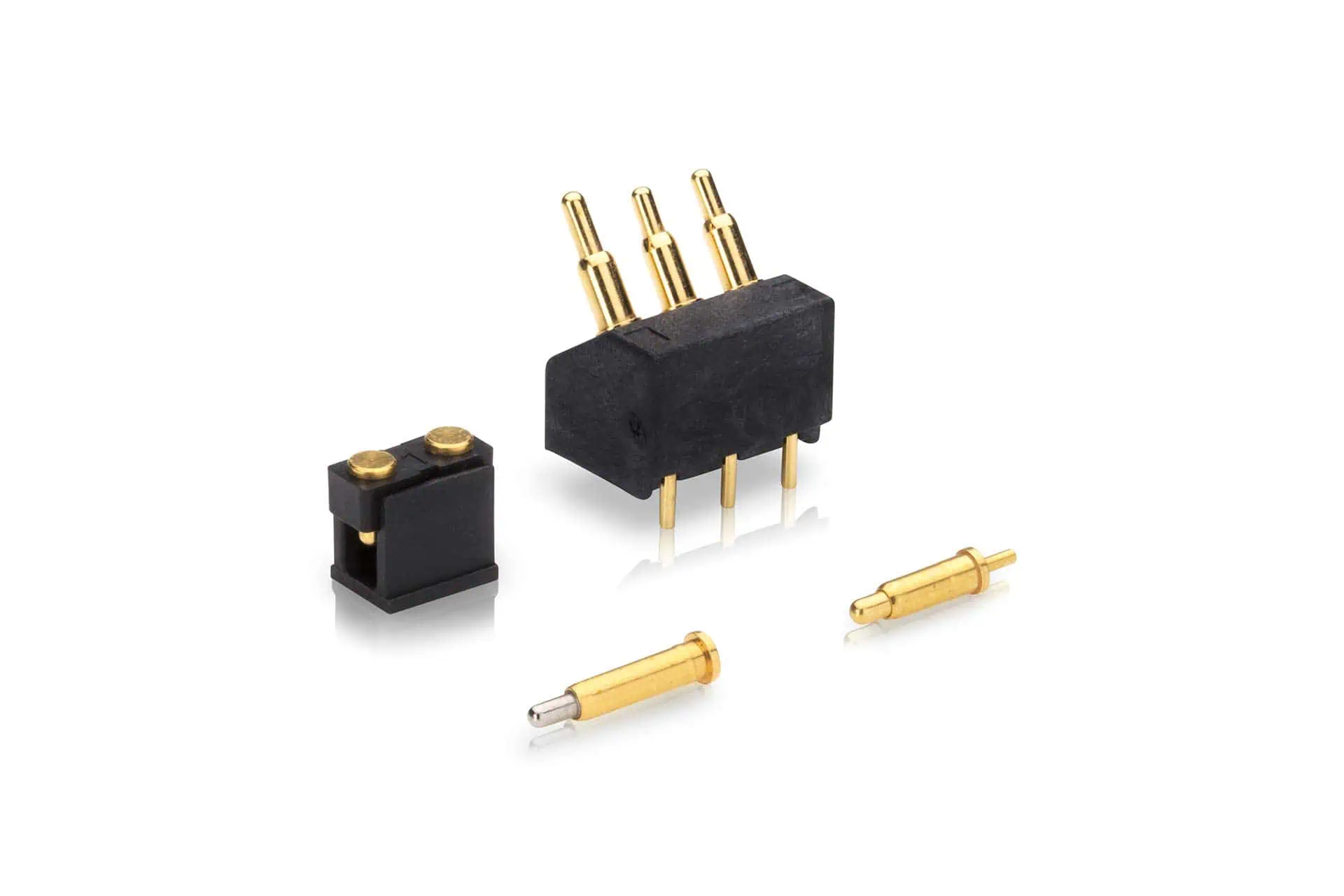
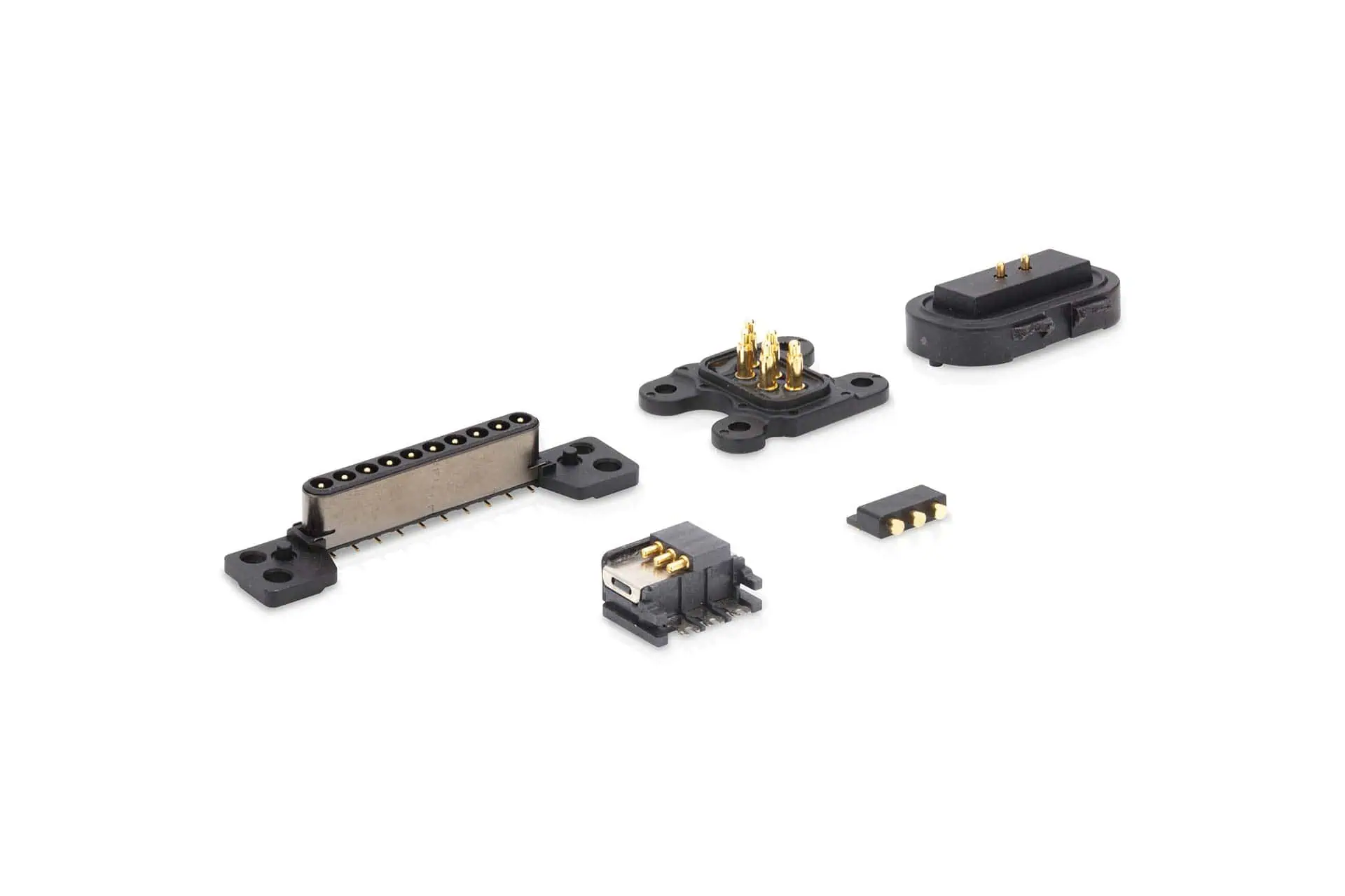
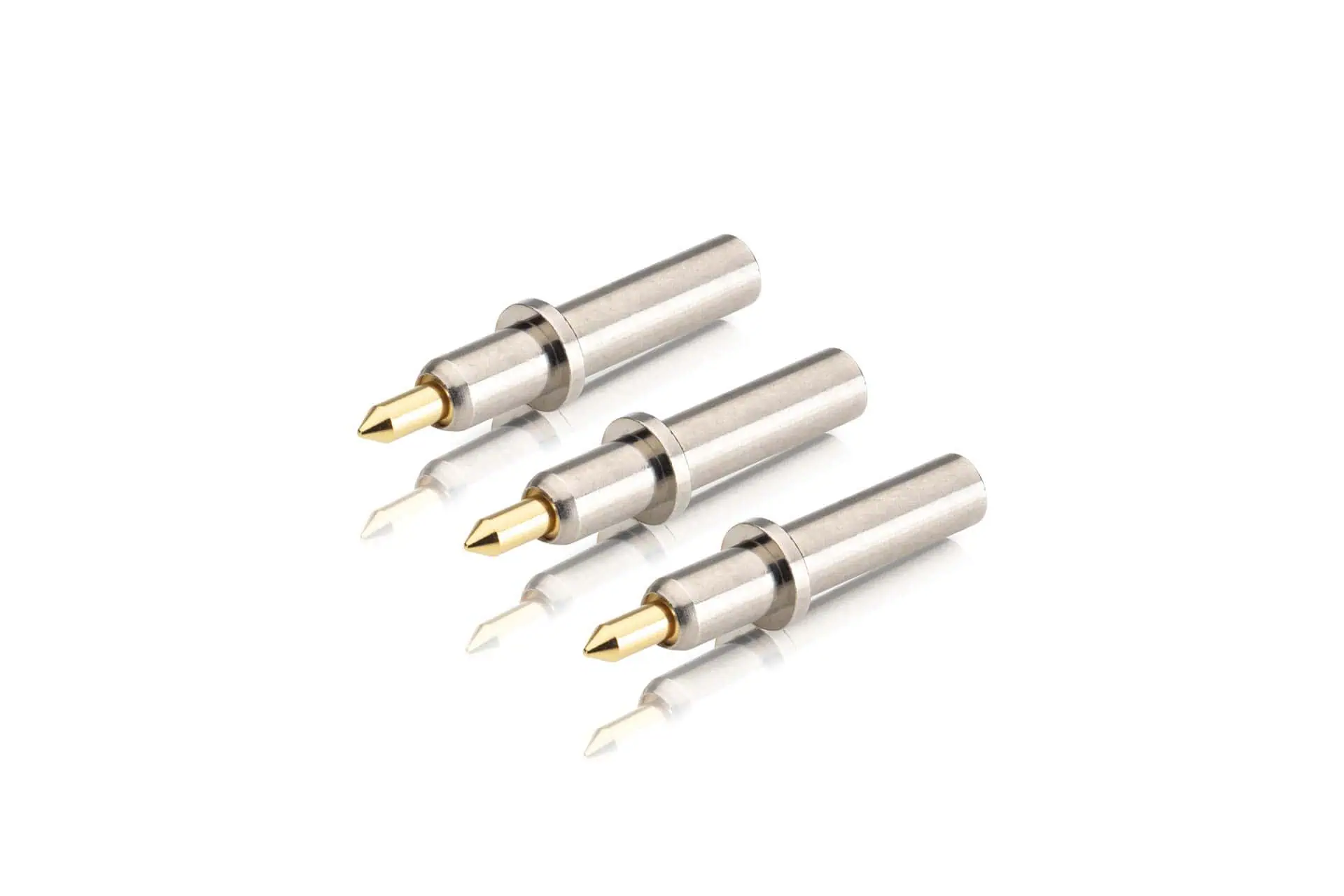
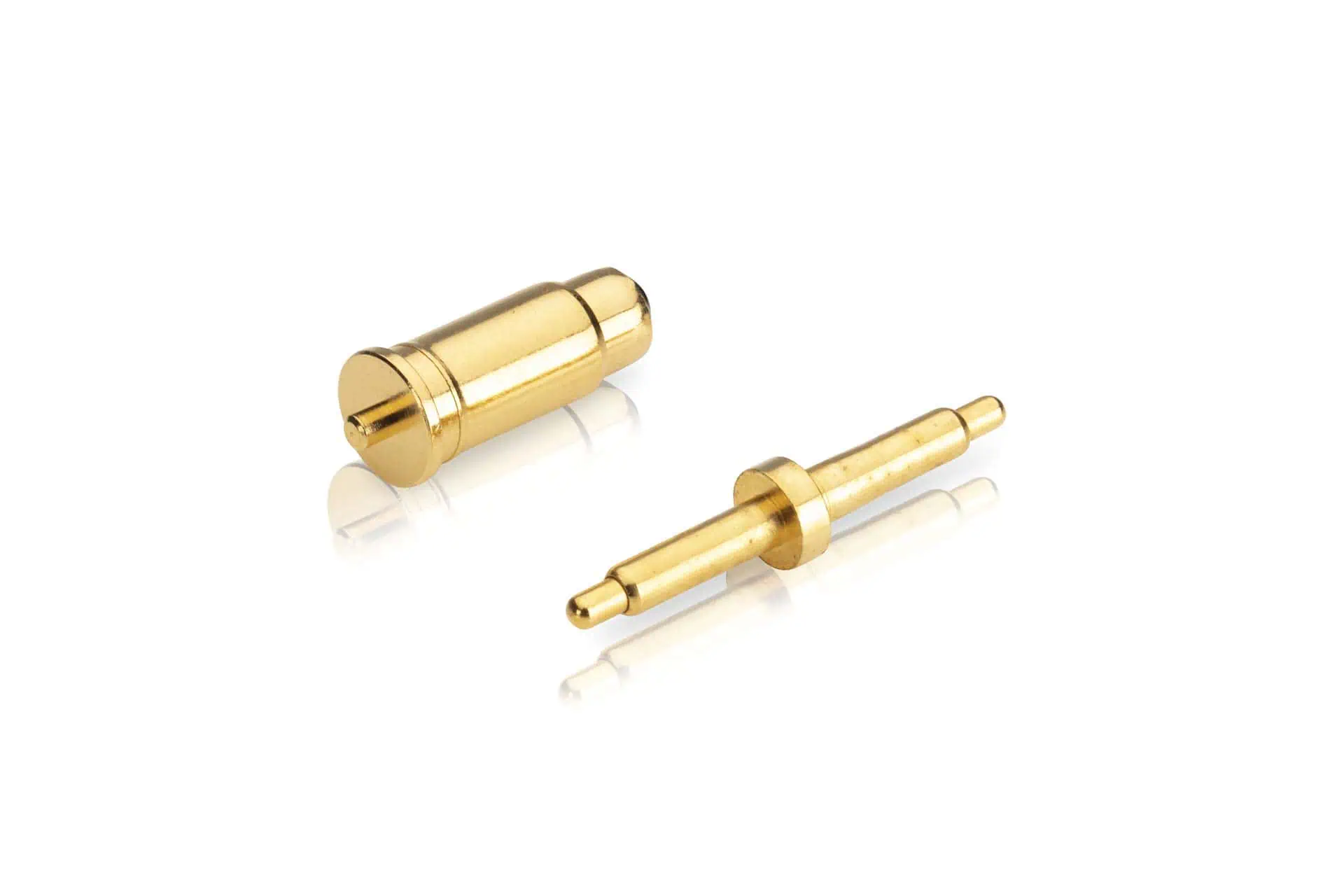
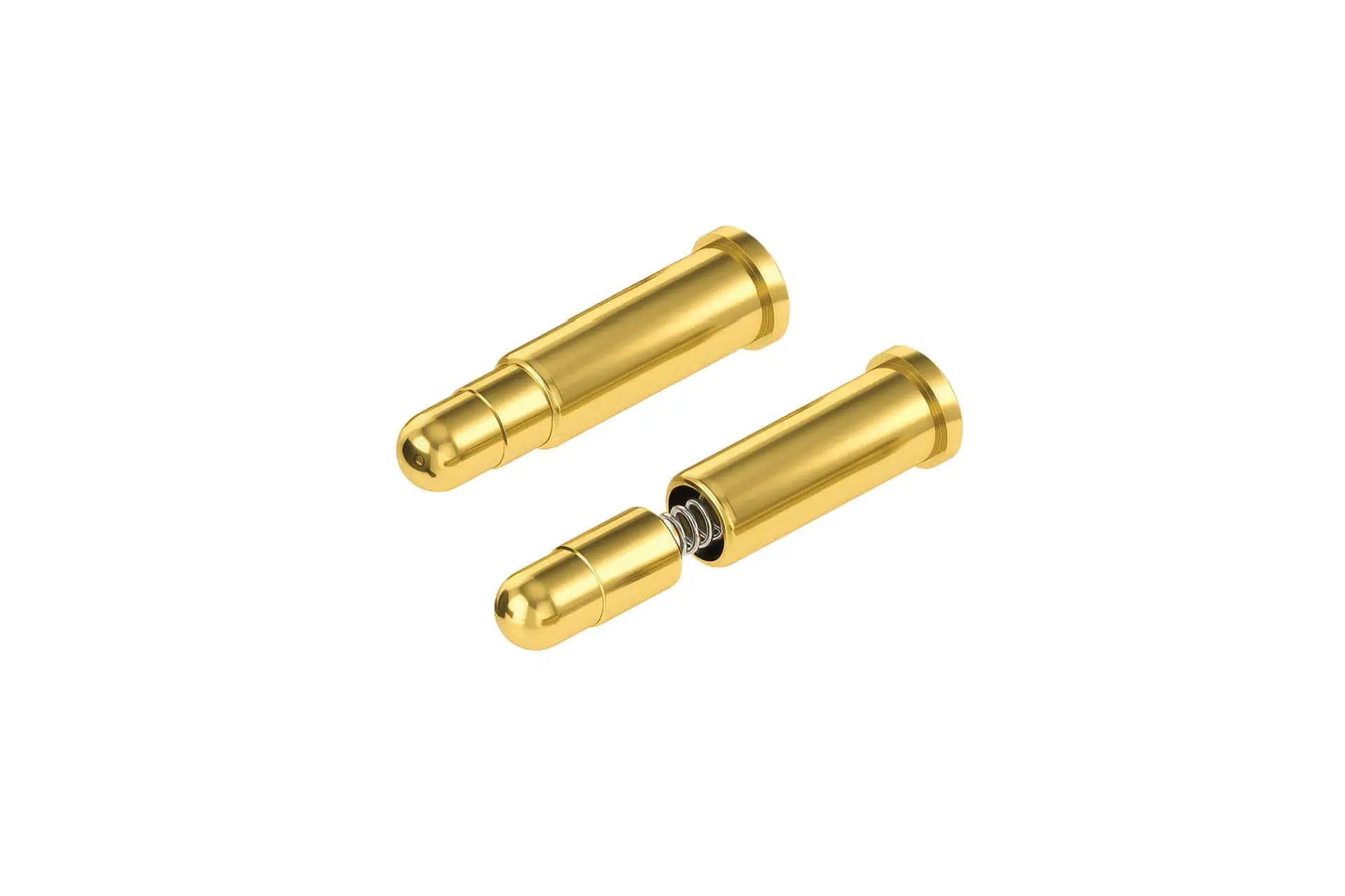
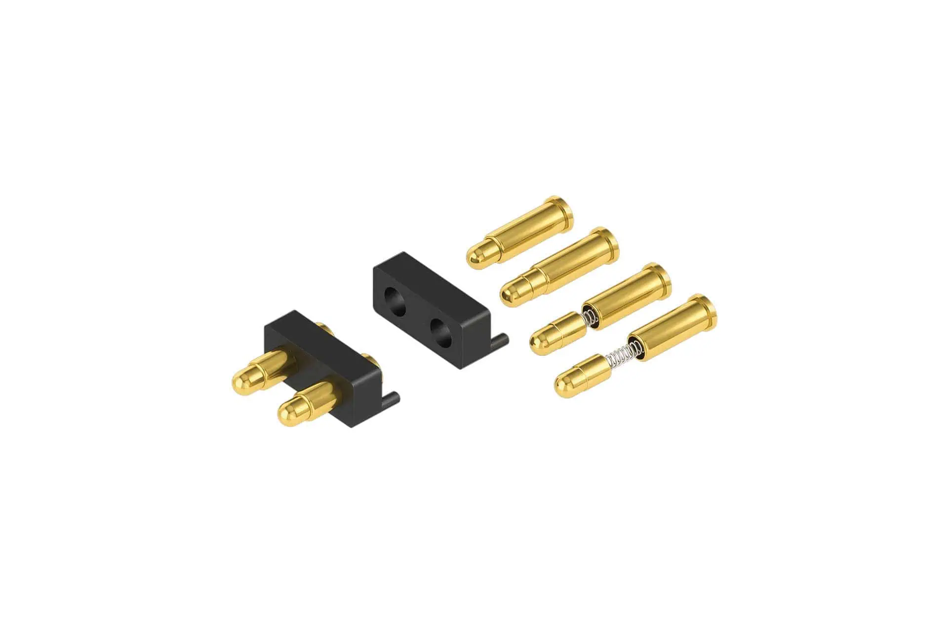
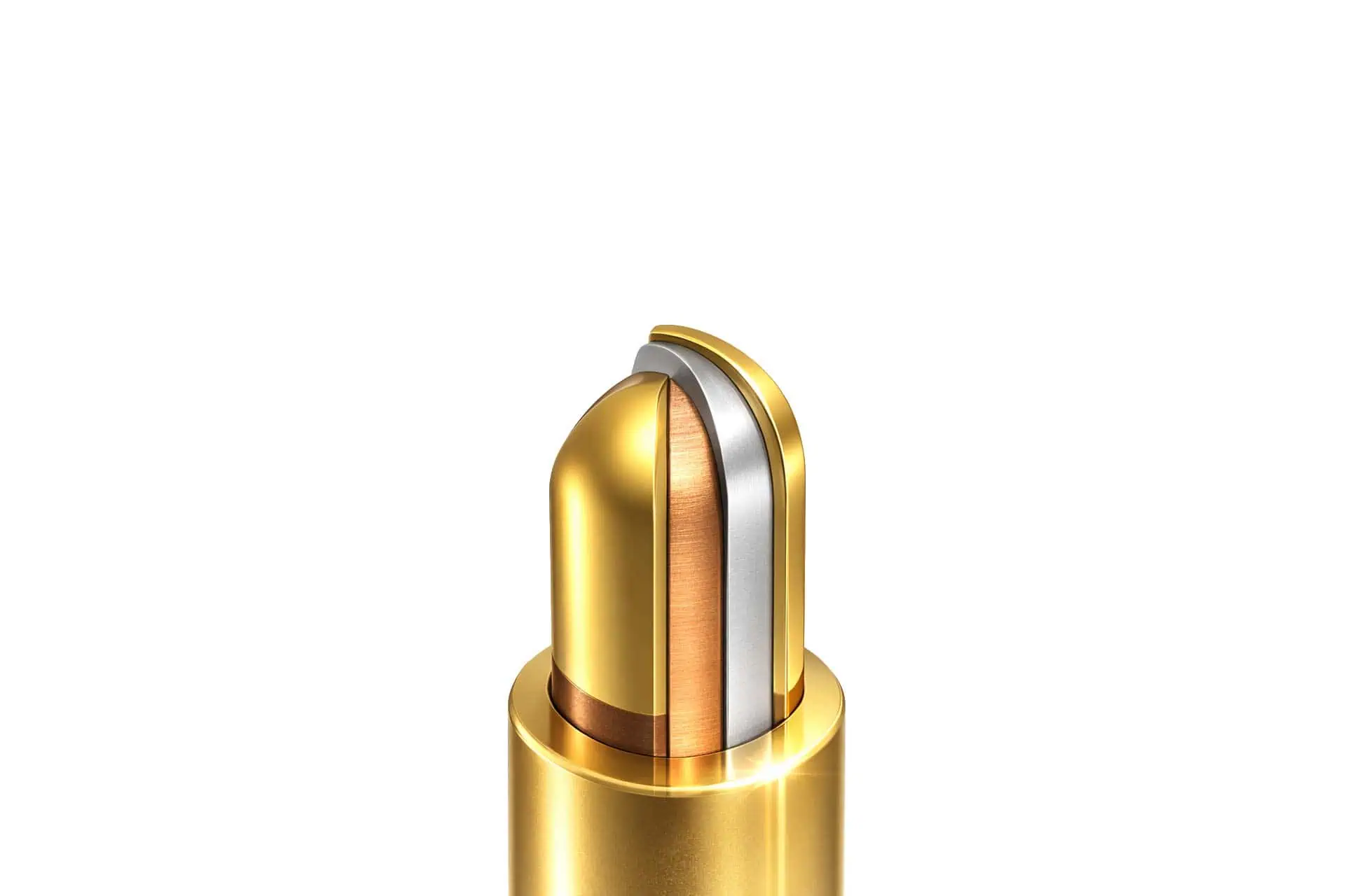
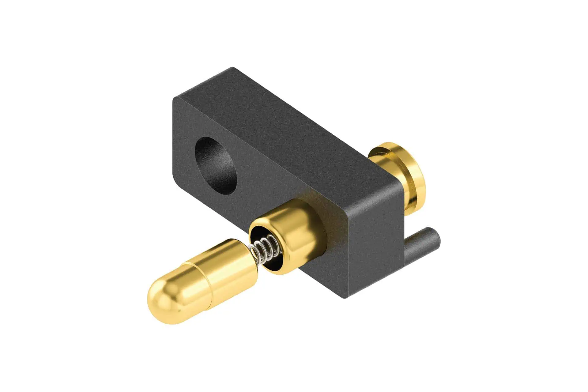
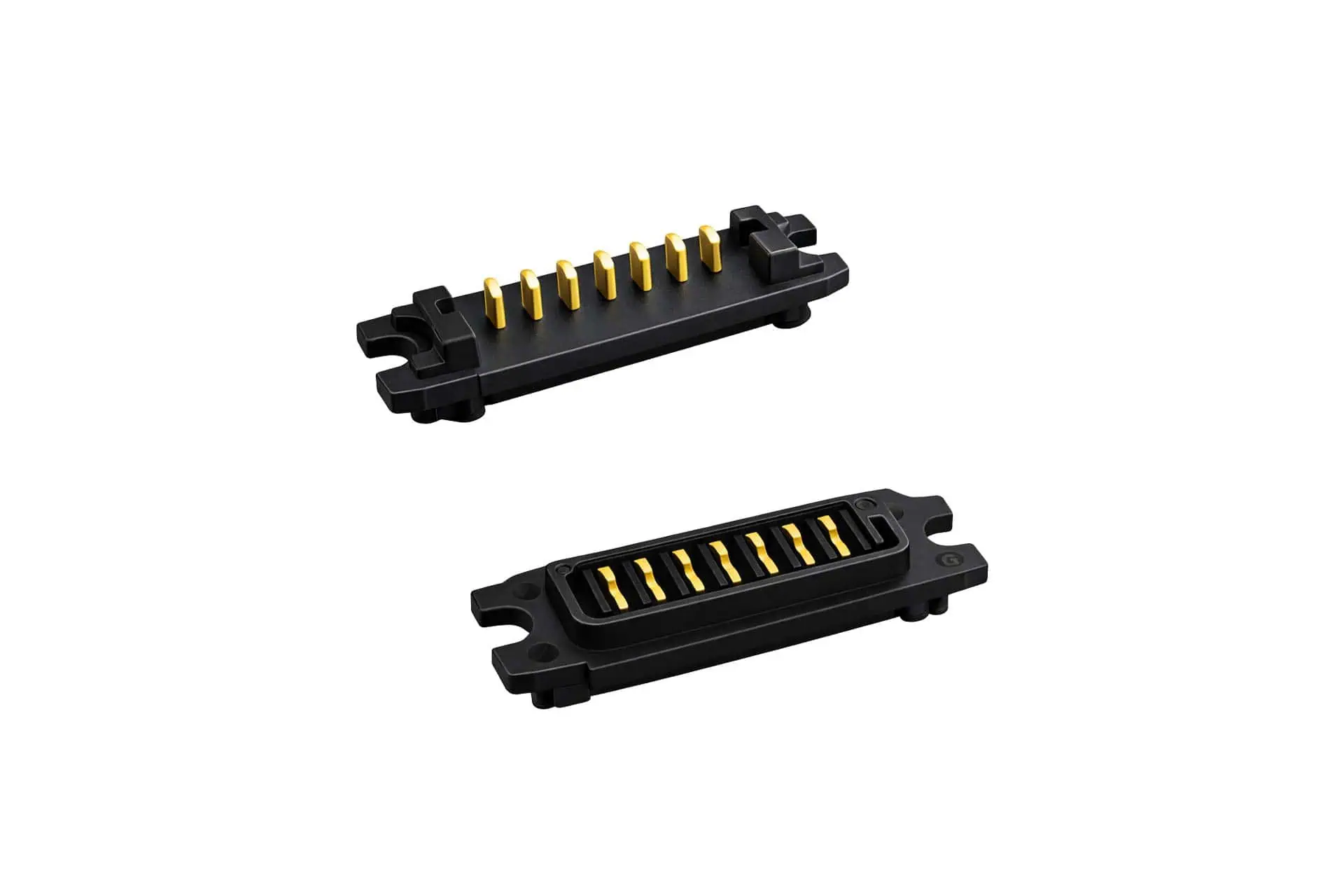
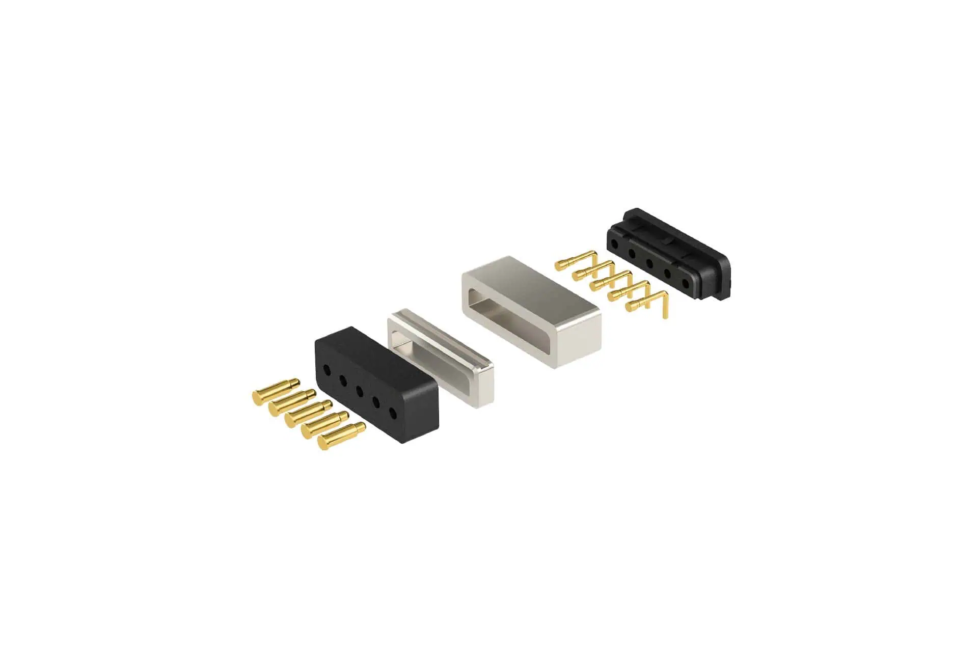
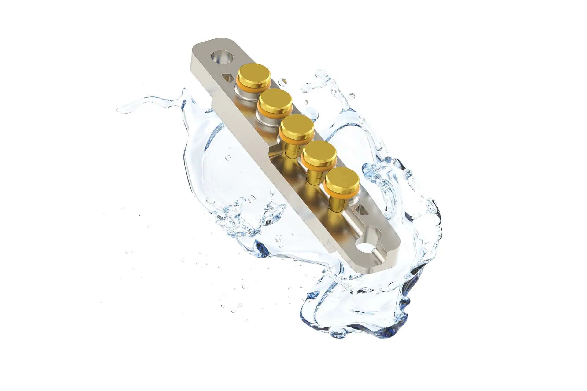
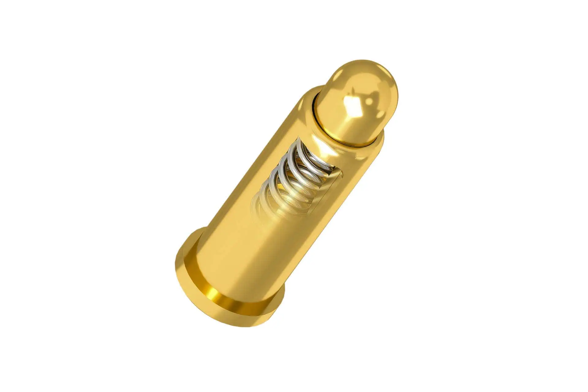
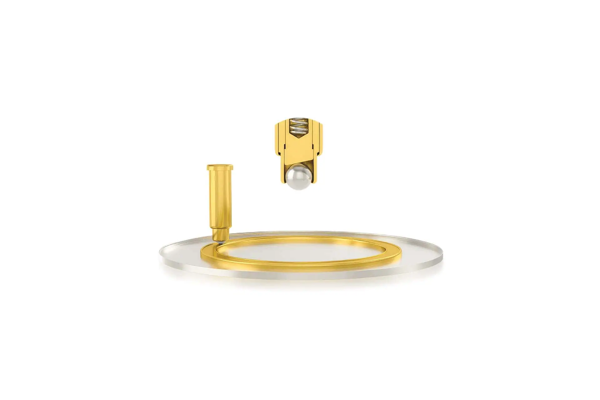
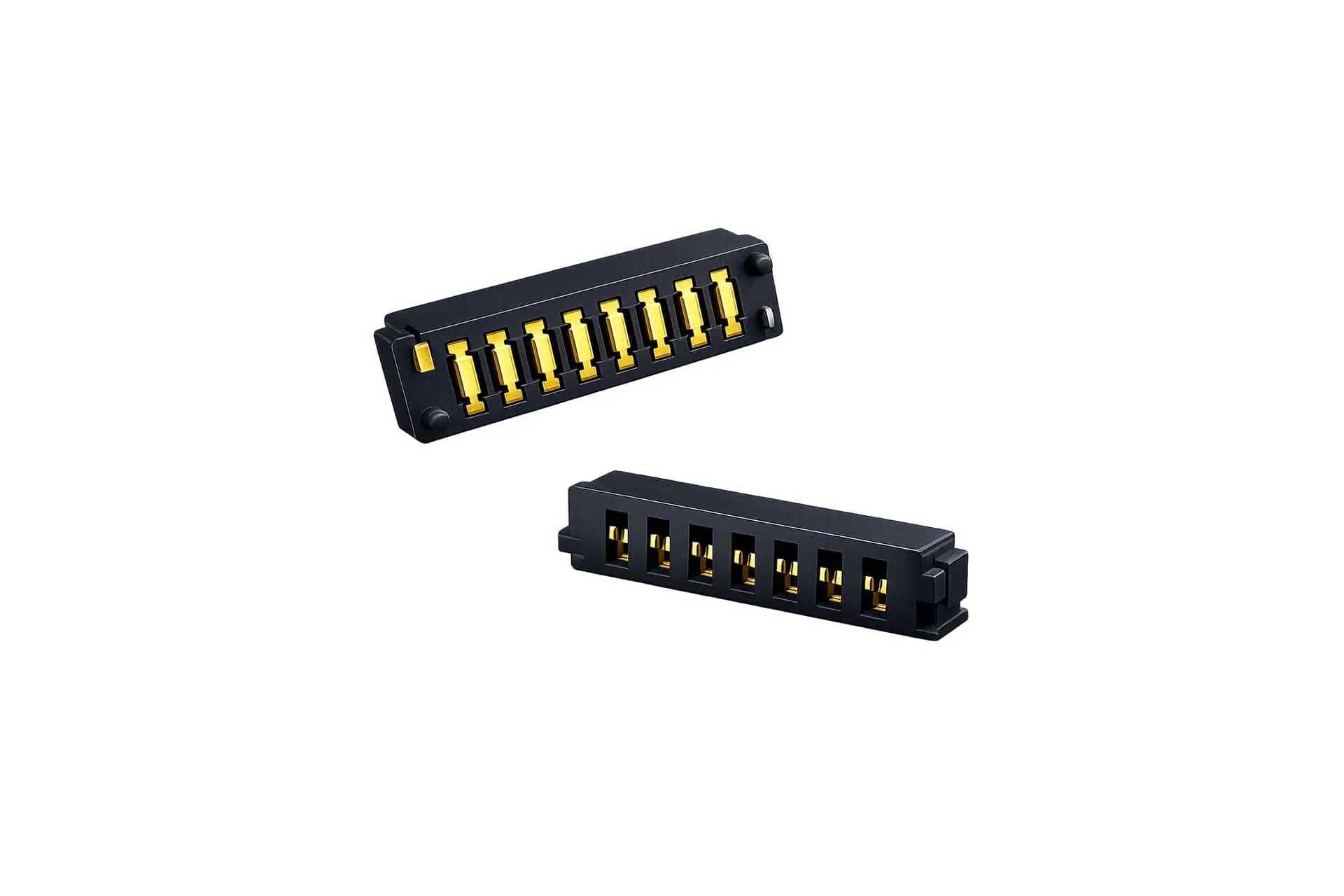
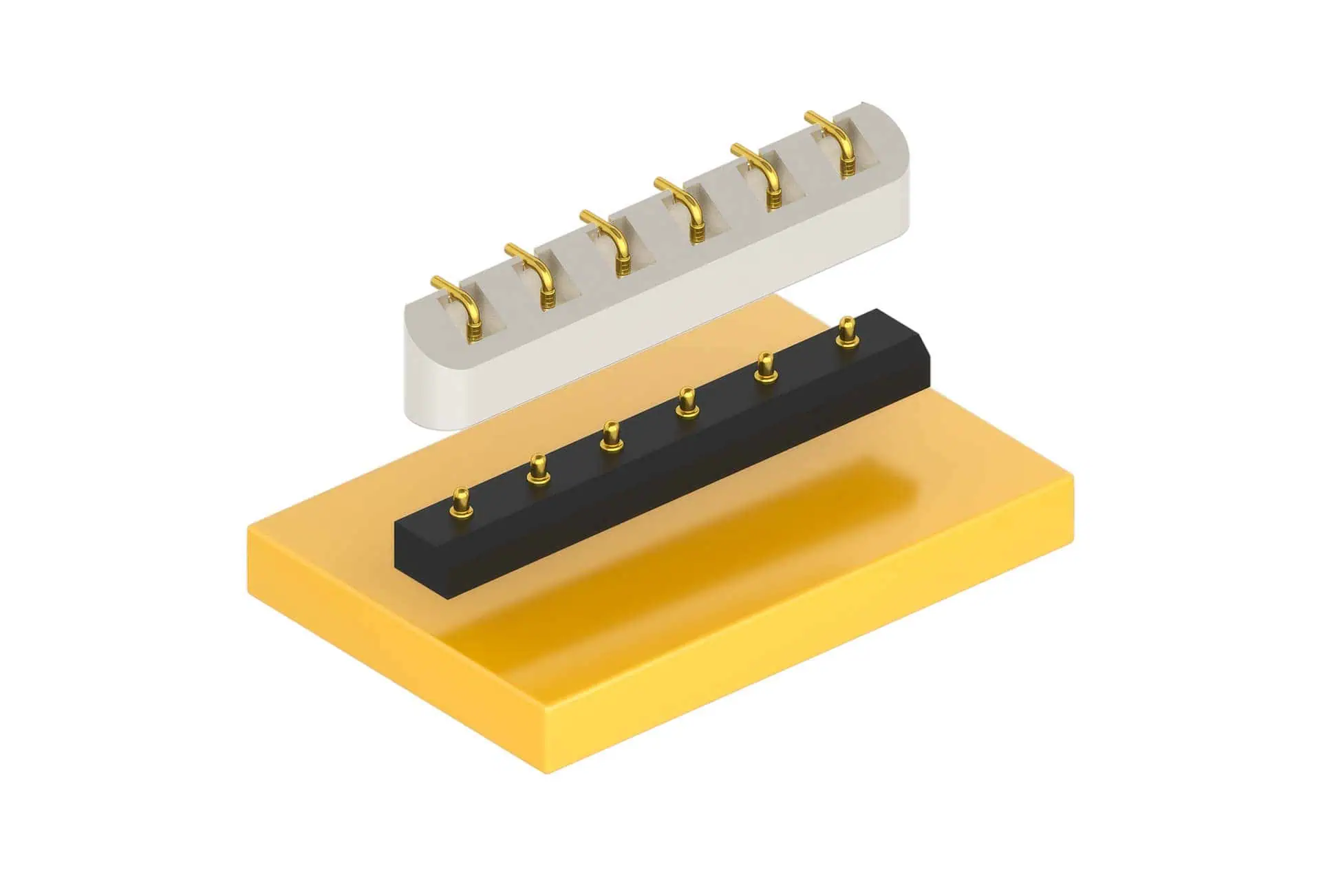
The examples shown provide an impression of possible pogo pin designs, contacting solutions and assembled interconnection elements. The specific design depends on the application, installation situation, contact requirements and technical framework conditions.
Send us your non-binding
product inquiry.
If you share the key requirements, we will propose suitable variants and check availability as well as alternatives.
Application: test, docking, modular interface, power, RF
Mounting: SMT/SMD (soldered), THT, connector, assembly
Mechanics: overall height, stroke, spring force, pin count/pitch (if known)
Environment: IP requirement, contamination/cleaning, temperature
Target values: current/signal, required cycles/service life
FAQs
What are pogo pins typically used for (testing, docking, modular systems)?
Typical applications include test systems/test fixtures (e.g. ICT/FCT, PCB contacting), docking (repeatable docking for charging/connection) and modular systems with defined contact points for interchangeable units. Depending on the application, magnetic guidance, IP protection or high-current/RF variants may also be used.
Which parameters are decisive for selection?
Typical selection criteria are current/voltage, contact resistance, stroke, spring force, pitch, tip geometry, plating, service life (contact cycles), environmental conditions (e.g. temperature, contamination, IP), mounting type (SMT/SMD or THT), and the nature of the mating contact surface.
Are there different form factors of pogo pins?
Yes. Common variants include standard pogo pins, high-current pogo pins, waterproof versions (e.g. IP67/IP68), magnetic pogo pin connectors and HF/RF-capable solutions. They also differ in tip geometries (e.g. crown/dome/flat) and mounting types such as SMT/SMD (reflow) or THT – as a single pin or as a contact assembly.
Are custom pogo pin solutions also possible?
Yes. Typical custom parameters include length, stroke, spring force, tip design, pitch, plating, insulation/sealing concept, and integration as a connector/assembly. In practice, this starts with a brief alignment of requirements (current, environment, service life, mating contact, assembly process), followed by samples/validation and final specification.
Can pogo pins be soldered (SMT/SMD or THT)?
Yes. There are SMT/SMD variants for reflow processes as well as THT versions for through-hole mounting. Important distinction: often the device under test is not soldered; instead, pogo pins are part of the test/docking hardware and contact the mating surface without a fixed solder joint on the counterpart (e.g. pads on PCBs).
How is contact resistance ensured?
A consistently low contact resistance is primarily achieved through the matched combination of plating/surface finish, often gold, contact force, suitable tip geometry and an appropriate mating contact surface. Defined compression, stroke and a mechanical design that minimises lateral forces and micro-movements are also important. Specific values depend on the design and should be checked against the datasheet and the application requirements.
What needs to be considered for high-current pogo pins?
For high-current applications, contact area/tip geometry, contact force, thermal behaviour, suitable material and plating combinations, and the mating contact surface are decisive. Stable mechanical guidance and sufficient margin against heating and voltage drop are also important. Current ratings depend on the design and should be tested/validated based on the datasheet and the application.
Are there waterproof pogo pins (IP67/IP68)?
Yes, there are versions with IP protection, e.g. for environments with moisture, splash water or cleaning processes. The achievable protection rating depends on the sealing concept, the integration (connector/assembly), the mating part and the real application (e.g. cycles, media, temperature).
What advantages do pogo pins offer over conventional connectors?
Pogo pins, also known as spring contact pins, enable compact and repeatable contacting for frequent docking or testing. With suitable mechanical guidance, they are more tolerant of small offset or angular deviations than conventional socket/plug pairs. They are also suitable for high mating cycles and support modular concepts in which units are regularly exchanged or docked.
Are pogo pins suitable for vibration or mobile applications?
In principle, yes – provided the interface is mechanically designed correctly. Key factors are guidance/support, appropriate contact force, suitable material pairing/plating, and a design that reduces micro-movements (fretting) and lateral forces. For demanding environments, redundant contacts, suitable tip geometries and a defined docking mechanism are used as required.
Are pogo pins suitable for automated assembly?
Yes, depending on the design. SMT/SMD pogo pins are typically designed for SMT processes (including reflow); footprint, coplanarity and solder paste deposition are particularly important. THT variants can also be processed automatically depending on the design. The right option depends on mechanical loads, available space, process requirements and volumes.
Are pogo pins suitable for HF/RF?
Yes, for certain applications there are RF-/HF-optimised contact solutions. Defined impedance routing, mechanical stability, suitable geometry and the connection method are decisive. Whether an RF solution is appropriate depends strongly on frequency range, layout and system requirements.
Does etronics support custom solutions?
Yes. etronics supports selection, variant comparison, sampling, procurement and custom pogo pin solutions.
What information is helpful for an enquiry?
Useful information includes application, mounting type, stroke, spring force, pin count, pitch, current or signal, environment, service life and required quantities.
Five good reasons to choose pogo pins from etronics
Engineering Support
We support you throughout development and the entire product lifecycle with our engineering expertise and years of experience.
Short development and Production times
Thanks to our large production capacities, we meet even demanding lead times and delivery schedules.
Quality is our top priority
We strictly follow established quality standards and apply rigorous selection and testing processes for our partners – including validation upon request.
Fast delivery from our Swiss warehouse
Our warehouse ensures your flexibility. For many customers, we hold stock and can deliver replenishments to their facility within two days.
Small series? No problem.
We also manufacture small and very small series of customized spring contact solutions – tailored to your specific needs.
How your requirement becomes the right pogo pin solution
1. Your inquiry
We clarify requirements, objectives and technical framework conditions.
2. Feasibility check & solution development
We evaluate suitable components, partners and solution approaches.
3. Customized quotation
You receive a clear recommendation with the relevant key details.
4. Project kickoff & Order placement
etronics continues to reliably support procurement, quality and delivery.
5. Prototyping & Sample production
Samples and prototypes are prepared so that function, fit and technical requirements can be verified.
6. Sample approval & Optimization
Feedback from testing and coordination is incorporated into the final design of the solution.
7. Series production & Quality assurance
After approval, production, testing and quality requirements for series delivery are coordinated.
8. Delivery & Logistics solutions
etronics reliably supports procurement, delivery and follow-up supply beyond the project itself.
Other products & solutions
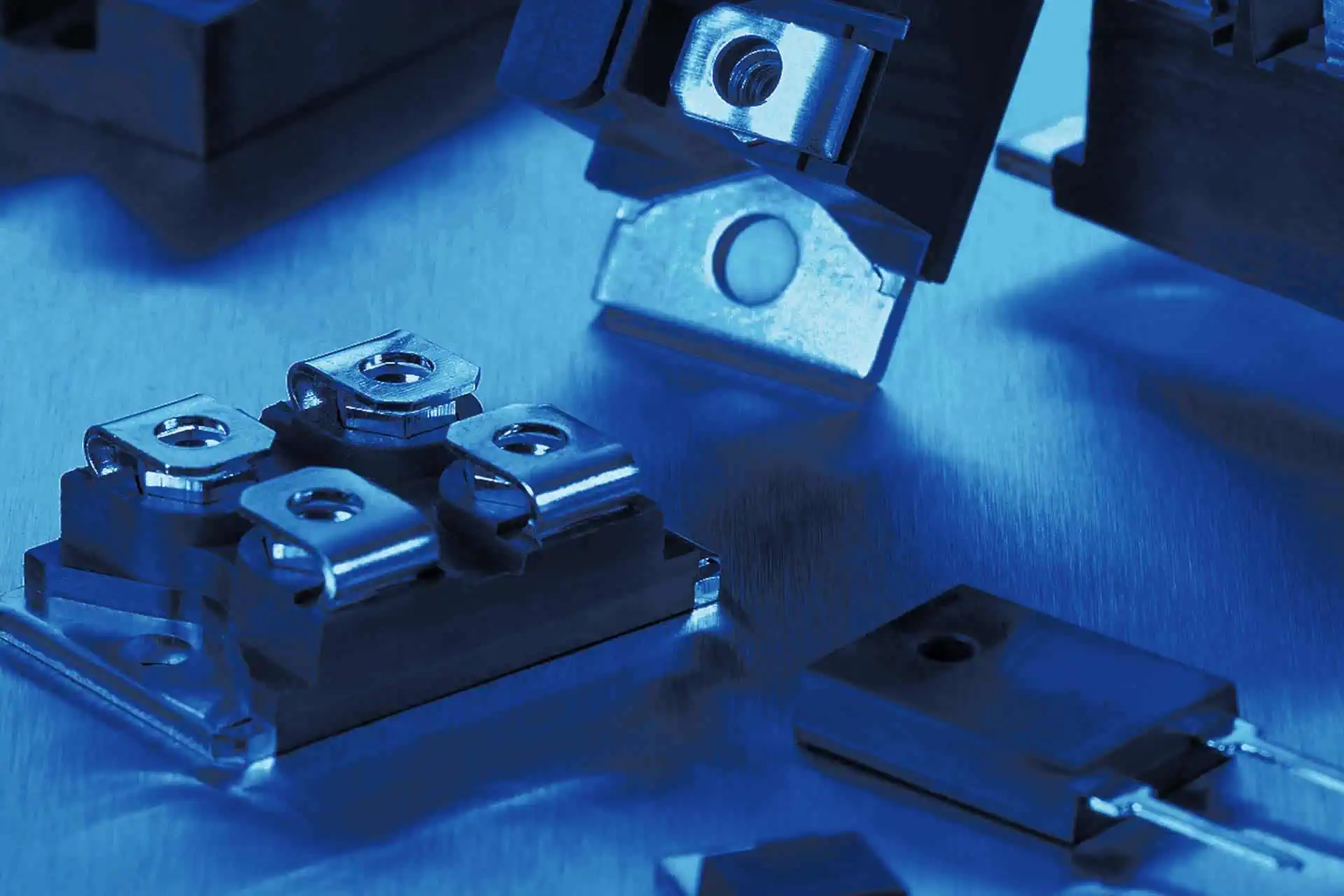
Resistors
Precision and power resistors – robust, compact and selected to suit the application.

Membrane keypads
Custom membrane keypads and front foils – robust, durable and precisely matched to your device design.

Custom Cable Assemblies
Cable assemblies for reliable connections – custom-manufactured and technically matched.

Displays
TFT, OLED and LCD displays for industrial applications – high-contrast, energy-efficient and individually customizable.

Touch Panels
Capacitive and resistive touch panels for devices and machines – precise, robust and easy to integrate.

Silicone Keypads
Silicone keypads for precise control panels and input solutions – tactile, robust, durable and customizable.

Printed Circuit Boards (PCBs)
Single- and multilayer PCBs, HDI, rigid-flex and aluminium PCBs – precisely manufactured for your application.
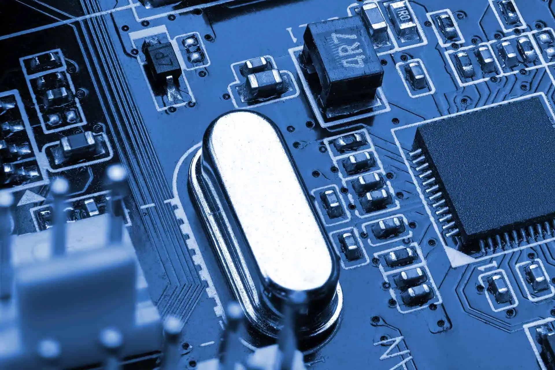
Crystals & Oscillators
Crystals and oscillators for reliable timing – frequency-stable, compact and available long-term.

Memory Components
SRAMs, PSRAMs and low-power memory for industrial electronics, embedded systems and long-life applications.

Cooling Solutions
Thermally optimized cooling solutions for electronics – from heat sinks and heat pipes to air and liquid cooling.